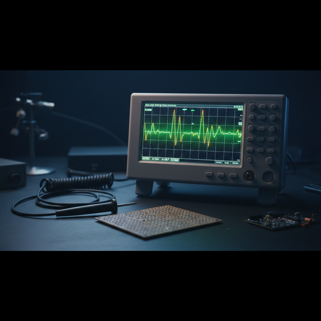
Oscilloscope with a glowing green waveform trace and a probe resting on a dark electronics bench
Matched To The Scope. True To The Signal. Quiet At The Tip.

Oscilloscope Probes for Every Bench, Board, and Bus

Passive, active, differential, and current oscilloscope probes for design and validation engineers, production test teams, field service technicians, and teaching labs. The probe is part of the circuit it measures, so matching it right is the difference between seeing the signal and seeing an artifact.

  • Passive x1/x10, active, differential, current and high-voltage
  • Bandwidth, loading and attenuation in plain terms
  • Scenario guidance: rails, ripple, high-side switching, mains
  • Compensation and grounding technique that keeps traces honest

The fundamentals

What an oscilloscope probe does, and why it is part of the circuit

An oscilloscope probe is the signal path between a node on a live circuit and the scope's input. It is not a glorified wire. A plain lead would add capacitance, pick up everything radiating nearby, and reflect fast edges back into the circuit. A probe is a designed transmission system: tip, damped cable, and termination, engineered so the waveform that reaches the scope still resembles the one on the board.

The uncomfortable truth of probing is that the probe becomes part of the circuit the moment the tip touches the node. Its input resistance and input capacitance appear in parallel with whatever you are measuring. That is called probe loading, and at high frequency the capacitive part dominates: 10 picofarads at 100 megahertz presents an impedance of only about 160 ohms to the node. Enough loading slows edges, detunes oscillators, and can stop a marginal circuit from misbehaving the moment you try to watch it.

This is why the classic x10 passive probe exists. A 9 megohm resistor at the tip forms a 10:1 divider with the scope's 1 megohm input, and the trimmer capacitance across it forms a matching capacitive divider. The circuit sees a lighter load, the scope sees one tenth of the amplitude, and the divider stays flat across frequency once it is compensated.

The working rule

Every measurement disturbs the thing it measures. The probe you want is the one whose disturbance is small enough not to matter for this signal, at this impedance, at this frequency. That is a different probe for a power rail than for a gigahertz clock, which is why a well equipped bench owns several.

Abstract glowing green waveform representing signal fidelity through an oscilloscope probe
Tip & head
Reaches the node: sharp tip, hook, or solder-in pigtail. The tip network sets the loading the circuit sees.
Cable
Low-capacitance, lossy coaxial cable designed to damp reflections rather than ring on fast edges.
Compensation box
Trimmer at the scope end (or tip) that matches the divider's RC time constants to that scope input.
BNC & readout
The connector, plus the sense pin many scopes use to detect attenuation and scale the display.

The families

Types of oscilloscope probe

Every probe family answers a different question: how much loading the circuit can tolerate, whether the measurement is referenced to ground, and whether the quantity of interest is voltage or current. These are the distinctions that matter when you pick one up.

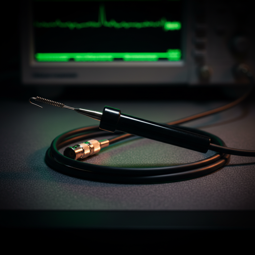
Passive x10 oscilloscope probe with cable coiled on a dark bench

Passive probes (x1 / x10)

The everyday workhorse

  • Rugged, inexpensive, no power required. The x10 position gives roughly 10 megohms and 10 to 15 picofarads of loading with bandwidth into the hundreds of megahertz.
  • The x1 position keeps full amplitude for small, slow signals but loads the node with the whole cable capacitance and limits bandwidth sharply.
  • Ground referenced only. The ground clip is bonded to safety earth through the scope chassis.
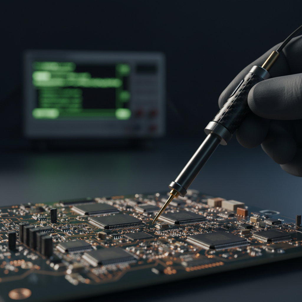
Active oscilloscope probe with amplifier head near a circuit board

Active single-ended probes

For fast edges and delicate nodes

  • A powered amplifier at the tip buys what passives cannot: input capacitance below a picofarad and bandwidth into the gigahertz.
  • The trade is a narrower voltage range, higher cost, and a head that deserves careful handling.
  • Usually tied to a scope family through a powered probe interface rather than a plain BNC.
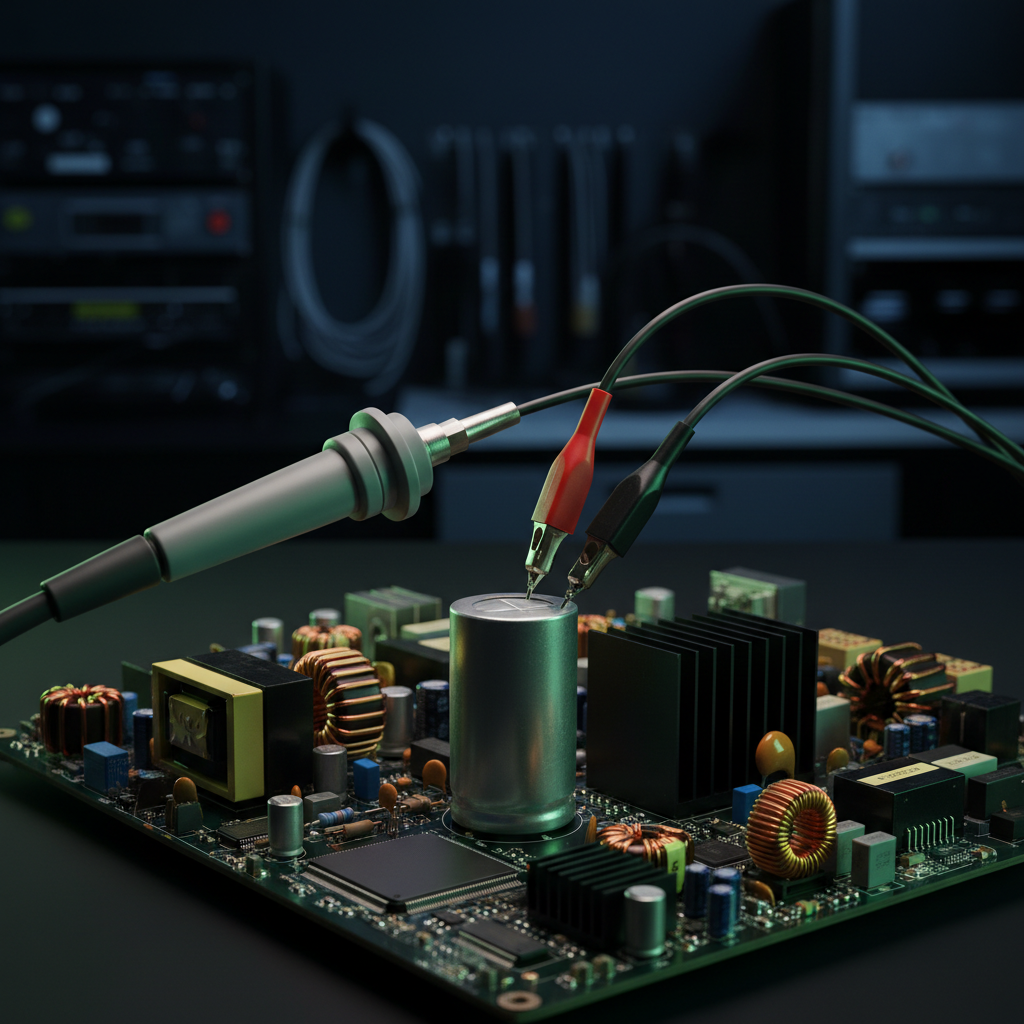
Differential probe with two input leads probing a power electronics board

Differential probes

When neither point is ground

  • Measures the voltage between two nodes and rejects what they share, so floating and high-side measurements become safe and honest.
  • Common-mode rejection ratio is the defining spec, and it always falls with frequency. Check it at your switching frequency, not at DC.
  • High-voltage differential versions are the standard tool for power electronics and mains referenced work.
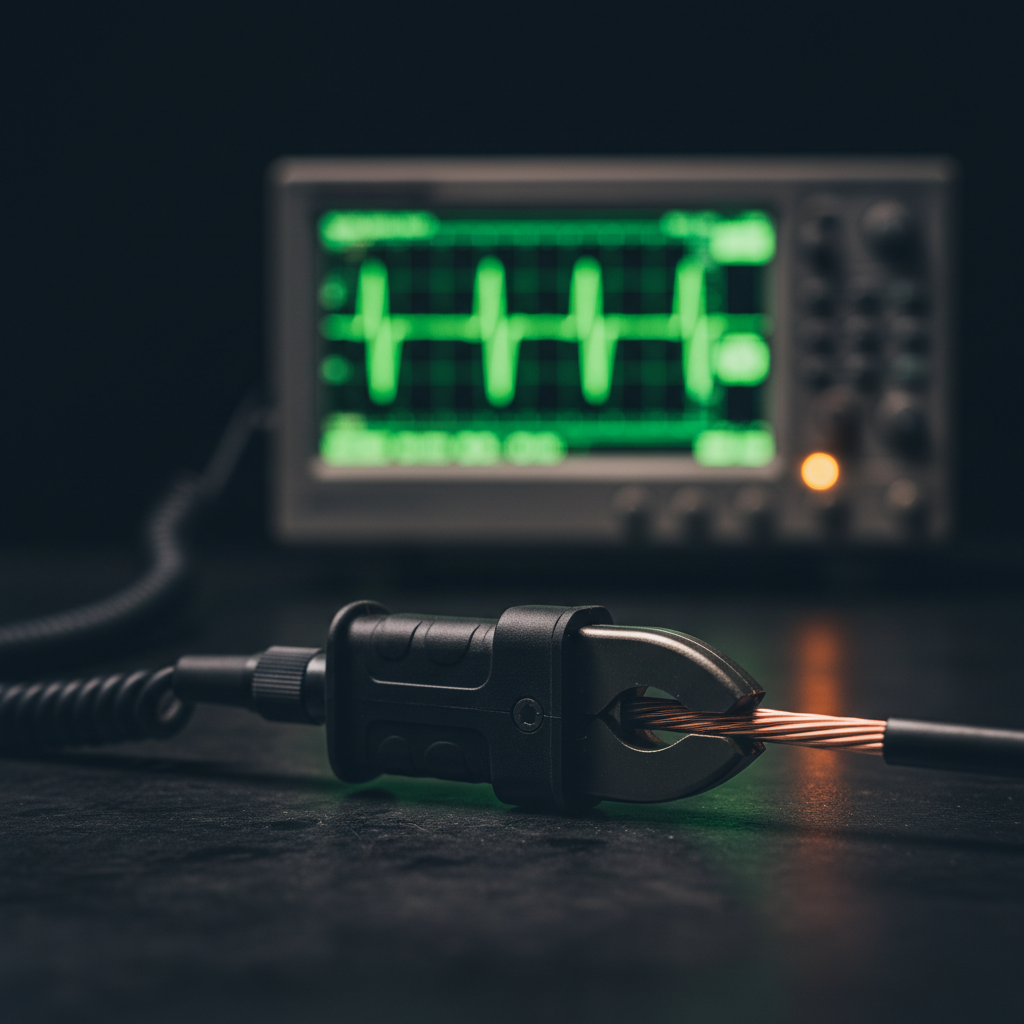
Clamp style current probe closed around a wire on a test bench

Current probes

Clamp the conductor, keep the circuit closed

  • A jaw closes around the conductor and senses its field. No break in the circuit, no shunt to design in.
  • Transformer types cover AC only; Hall-effect hybrid types measure down to DC. Zero or degauss before each session.
  • Sensitivity, bandwidth and maximum current trade against each other. Small currents may need multiple turns through the jaw.

High-voltage probes

Respect the derating curve

Above the reach of a standard passive probe sit dedicated high-voltage probes: 100:1 and 1000:1 passive designs for ground referenced measurements, and high-voltage differential probes for everything floating. Two things define this category. The first is the derating curve: the headline voltage rating applies at DC and low frequency and falls steeply as frequency rises, so a probe that is fine on a DC bus can be over-stressed by the ringing on a switch node.

The second is the measurement category (CAT) rating, which describes the transient environment the probe may legally and safely connect to. Work on mains circuits belongs to probes rated for the category of the point of connection. Neither spec is a formality; both assume you have read them before the tip touches anything energized.

Reading the data sheet

The specifications that actually matter

Probe data sheets carry a page of numbers. A handful decide whether the measurement is trustworthy. Here is what each one governs, and the trap that comes with it.

Key oscilloscope probe specifications, what each one governs, and what to watch for
SpecificationWhat it governsWhat to watch for
BandwidthThe frequency at which the probe's response is down 3 dB. Sets how fast a signal the probe can pass without visibly rounding it.Probe and scope form a system, and system bandwidth is lower than either alone. At the 3 dB point the displayed amplitude is already about 30 percent low, so leave margin rather than measuring at the limit.
Rise timeThe fastest edge the probe can convey. Roughly 0.35 divided by bandwidth for typical responses.The displayed rise time is the combination of signal, probe and scope. If they are similar, the screen is showing you your instruments, not your circuit.
AttenuationHow much the signal is divided before the scope: x1, x10, x100, x1000. Trades sensitivity against loading and voltage range.The scope must know the factor to scale the display. A readout pin the scope ignores, or a switch left in the wrong position, produces readings ten times off.
Input resistanceThe DC loading on the node, typically 10 megohms for a x10 passive probe at the tip.Matters most on high impedance nodes: bias networks, feedback dividers, sensor outputs. A 10 megohm probe on a 1 megohm node still moves it by roughly 9 percent.
Input capacitanceThe AC loading. Dominates at high frequency, where a few picofarads can be a few hundred ohms.This number is the honest difference between probe classes. Passive x10 probes sit around 10 to 15 picofarads; good active probes sit below one.
Compensation rangeThe span of scope input capacitance the probe's trimmer can be adjusted to match.If your scope's input capacitance falls outside the range, the probe can never be made flat on that scope. Check before buying third-party probes.
Maximum input voltage & deratingThe voltage the probe tolerates, quoted at DC or low frequency, with a curve showing how it falls as frequency rises.The derating curve is the real rating. Switch node ringing and fast transients live exactly where the curve has fallen furthest.
CMRR (differential probes)How well a differential probe rejects the voltage common to both inputs.Always quoted best at DC and falling with frequency. Judge it at your switching frequency and its harmonics, because that is where the common-mode energy is.

Rule of thumb: five times the signal

For amplitude measurements you can trust, aim for a probe-plus-scope system bandwidth around five times the highest frequency of interest. For digital work, size to the edge rate rather than the clock: the energy that shapes a fast edge lives well above the clock frequency.

The system, not the probe

Every figure above describes the probe and scope together. A wide-band probe on a narrow scope, or the reverse, performs like the weaker of the two. Buy, compensate, and evaluate them as a pair.

Match the tool to the measurement

Choosing the right probe for the job

Start from the measurement, not the drawer. Each scenario below names the probe that usually wins and the reason it wins.

General digital debug

x10 passive probe

The default for logic levels, resets, buses and everyday troubleshooting. Light enough loading for most digital nodes, rugged enough to live on the bench, and honest once compensated. Move up to active probes when edges outrun it.

Power rail ripple & noise

x1 passive or a dedicated power-rail probe

Millivolts of ripple on volts of DC is a sensitivity problem, and a x10 probe throws away a factor of ten before the scope's noise floor. A x1 probe keeps the amplitude for low frequency ripple; dedicated power-rail probes add DC offset range and low noise for tight rails.

High-side switching & gate drive

Differential probe

The gate to source of a high side FET, or the voltage across a high side shunt, is not ground referenced. A differential probe reads the difference directly. Floating the scope to fake it puts lethal voltage on the chassis.

Mains & offline supplies

CAT-rated high-voltage differential probe

Anything referenced to the line belongs to a probe with a measurement category rating for the point of connection and a voltage rating that survives the derating curve at your frequencies. Standard bench passives have neither.

Fast edges & RF nodes

Active probe

Sub-picofarad loading and gigahertz bandwidth keep the probe from becoming the dominant capacitance on the node. On matched 50 ohm paths, a direct 50 ohm input connection can beat any probe.

EMC debugging & currents

Current probe

Chasing conducted emissions, inrush, or a supply current waveform is a current measurement; make it with a clamp instead of inferring it from voltage drops. Pair with a differential probe across a shunt where a jaw cannot reach.

If the trace looks wrong, suspect the probing first

Ringing on every edge, mysterious offsets, amplitude that changes when you move your hand: these are probing artifacts more often than circuit faults. Re-check compensation, shorten the ground return, and confirm the attenuation factor before redesigning anything.

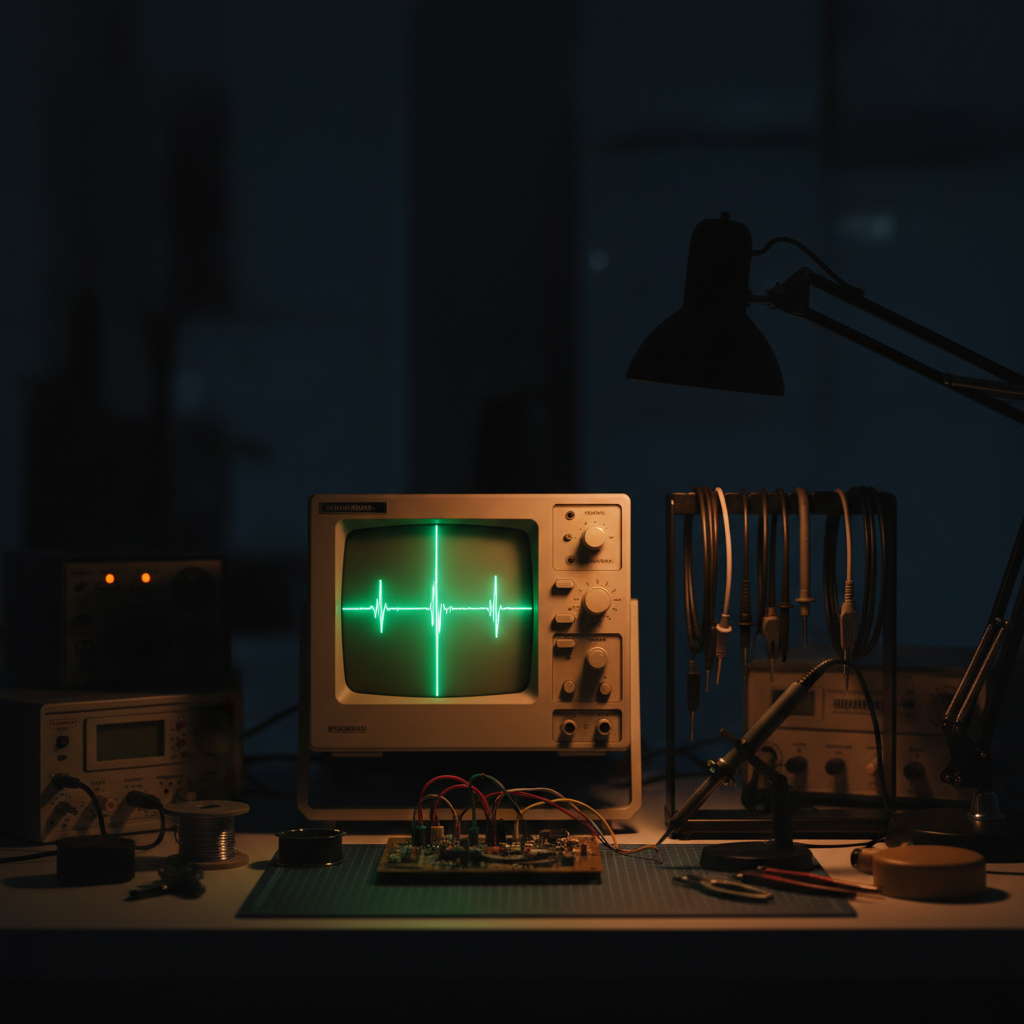
Engineer's test bench with an oscilloscope, probes and a circuit board under measurement

Technique

Care and accuracy: the habits that keep traces honest

Compensate, then trust

Clip the tip to the scope's calibration output and adjust the trimmer until the square wave is flat-topped: no overshoot, no rounding. An uncompensated x10 probe misreads amplitude across a wide band while looking perfectly plausible. Recheck whenever the probe changes scope or channel.

Shorten the ground return

The six-inch alligator ground lead is the single biggest source of false ringing on fast edges. Its loop inductance resonates with the probe's input capacitance. Fit the spring ground for anything with sharp edges, and treat the long clip as a convenience for slow work only.

Use the tip accessories

Spring grounds, SMD grabbers, browser tips for fine-pitch parts, and solder-in pigtails for measurements you will repeat. A pigtail soldered to the node with a short ground gives the most repeatable connection a passive probe can make.

Handle it like an instrument

Probe cables hide a fine resistive center conductor that does not survive being crushed, kinked, or yanked out by the cord. A damaged cable degrades bandwidth and response invisibly. Coil loosely, hang by the head, and retire probes that have been run over by a chair.

Stay inside the ratings

Check maximum voltage against the derating curve at the frequencies actually present, not just the DC value. On differential probes, confirm the common-mode range too. Ratings assume an undamaged probe: inspect tips and leads before high-energy work.

Who reaches for them

Applications across the bench

The same families of probes serve four very different working days. What changes is which specs dominate and how hard the probes are used.

Development bench with oscilloscope and probes during design validation work

Design & validation engineers

Characterizing new hardware: signal integrity on fast edges, power rail sequencing and ripple, jitter and timing margin. This is where active and differential probes earn their price, because the measurement has to be better than the circuit under test.

Production test

Repeatable, fixtured measurements at volume. Probe durability, consistent tip contact, and identical compensation across stations matter more than the last decibel of bandwidth. Solder-in pigtails and fixtured connections replace hand probing wherever a node is tested every shift.

Field service & repair

Diagnosing equipment where it lives: drives, power supplies, controls, audio and RF gear. Rugged passive probes carry the day, with a CAT-rated differential probe in the kit for anything line-powered. The discipline is knowing which nodes are safe for which probe before opening the case.

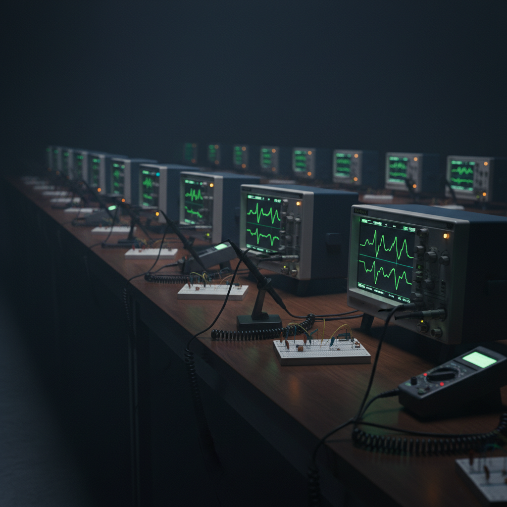
University electronics teaching lab bench with oscilloscopes and probes

Education & teaching labs

Where probing habits are formed. Students who learn compensation, x1 versus x10, and short ground returns on day one stop fighting phantom ringing for the rest of their careers. Fleets of sturdy passive probes with intact accessories are the backbone of a working lab.

Common questions

Oscilloscope probe FAQ

What is the difference between a x1 and a x10 probe?

A x1 probe passes the signal straight through, so the scope sees the full amplitude, but the entire cable capacitance and the scope input hang directly on the circuit and bandwidth is limited to the low tens of megahertz at best. A x10 probe divides the signal by ten through a 9 megohm resistor at the tip, which cuts loading dramatically and extends bandwidth to hundreds of megahertz. The x10 position is the right default for almost everything; x1 earns its place only on small, slow signals where the extra sensitivity matters more than the loading. On switchable probes, check the switch position and make sure the scope's readout matches it.

Why does a x10 probe load the circuit less than a x1?

The 9 megohm tip resistor, with a small trimmer capacitor across it, sits between the circuit and everything else. Instead of driving the full cable capacitance plus the scope's input directly, the circuit sees roughly 10 megohms in parallel with about 10 to 15 picofarads. At high frequency, where capacitance dominates loading, that is the difference between a node that keeps behaving and one that gets dragged around by the measurement.

Can I use any probe with any oscilloscope?

Not safely, and often not at all. A high impedance passive probe needs a 1 megohm scope input, and its compensation range must cover that scope's input capacitance or it can never be adjusted flat. Some high bandwidth scope inputs are 50 ohm only and will not work with a standard passive probe. Active, differential and current probes with proprietary interfaces carry power and data through the connector and only work with the scope families they were designed for.

Are BNC probes interchangeable between scope brands?

Generic passive BNC probes usually are, provided the compensation range covers the scope's input capacitance and the input is 1 megohm. The small readout pin around the BNC that tells the scope the attenuation factor is not universal, so a probe from another brand may display amplitudes ten times off until you set the attenuation factor manually in the channel menu. Proprietary probe interfaces do not cross brands at all.

When is a differential probe mandatory?

Whenever neither of the two points you care about is ground. Classic cases are the voltage across a high side current shunt, the gate to source voltage of a high side transistor in a bridge, mains referenced nodes in an offline power supply, and motor drive outputs. The wrong answer is floating the scope by defeating its safety earth. That puts the chassis, and everything conductive connected to it, at circuit potential.

How much probe bandwidth do I need?

A common rule of thumb is a measurement system bandwidth of about five times the highest signal frequency you care about, which keeps amplitude error on harmonics small. For digital signals, size to the edge rather than the clock: a widely used approximation is bandwidth equals 0.35 divided by the rise time you need to resolve. Remember that the probe and scope form a system, and the combined bandwidth is always lower than either number on its own.

What does probe compensation actually do?

A x10 passive probe is a divider built from resistances and capacitances, and it is only flat across frequency when the two RC time constants match. The compensation trimmer adjusts that match against the scope's own input. Clip the probe to the scope's calibration output and adjust until the square wave has a flat top with no overshoot or rounding. Recheck whenever the probe moves to a different scope, or even a different channel.

Why does the long ground clip make edges ring?

The alligator ground lead and the probe tip form a loop, and that loop's inductance resonates with the probe's input capacitance. The result is ringing superimposed on every fast edge, often in the tens to low hundreds of megahertz, that is an artifact of the probing rather than a property of the circuit. Shortening the ground return, ideally to a spring ground fitted right at the tip, pushes the resonance up and out of the band you are measuring.

Can I measure mains with a standard passive probe?

Treat the answer as no. A standard passive probe's maximum voltage rating derates steeply with frequency, its ground clip is bonded to safety earth through the scope, and it carries no measurement category rating for the transient environment on a mains circuit. Line powered and mains referenced work belongs to high voltage differential probes with the appropriate CAT rating for the point of connection, used with the derating curve in front of you.

Do current probes require breaking the circuit?

Clamp style current probes do not. The jaw closes around the conductor and senses the field, with transformer types covering AC only and Hall effect hybrid types measuring down to DC. Zero or degauss the probe before measuring, and keep the conductor centered in the jaw. Where a clamp does not fit, the alternative is a shunt resistor read with a differential probe, which does mean designing the shunt into the circuit.

Get a Quote

Tell us about the measurement

Send the basics and we will point you in the right direction: the signals you need to see, their bandwidth and voltage levels, the scope they will connect to, and the quantities involved.

Specifying probes

Working out whether passive, active, differential or current probes fit the measurements you make.

Matching scope and probe

Confirming compensation range, input impedance and interface compatibility before anything is ordered.

Outfitting a bench or lab

Probe sets, spares and accessories for a new bench, a production line, or a teaching lab fleet.

We use what you submit to respond to your enquiry, which can include sharing it with suppliers who can quote your request. See our privacy notice.